The antenna has an aluminium parabolic reflector. The reflector is spray painted. Standard colour is grey RAL7038. The mount is made of hot dip galvanised steel. All screws, nuts and washers are made of stainless steel A4 or hot dip galvanised steel class 8.8. Depending on frequency band the feed is made of brass or hot dip brazed aluminium.
The antenna is delivered with two support stays for installation at the rim of the reflector. For additional security and stability one additional optional support stay may be connected.Further information is given in the installation manual.
Weight and dimensions
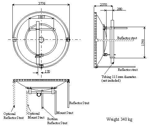
Dimensions in mm according to figure 1.
Figure 1 Dimensions
Interface
115 mm column with a minimum length of 1515 mm.
Alignment
Coarse Azimuth+ 50o (depends on column installation)
Fine: Both planes+5o
Environment
Wind
Survival without permanent deformation
Normal DutyWind speed up to 55 m/s and 25 mm radial ice.
Maximum deflection at 30 m/s is 0.3 times the -3 dB beamwidth.
Heavy DutyWind speed up to 70 m/s and 25 mm radial ice.
Maximum deflection at 45 m/s is 0.3 times the -3 dB beamwidth
Temperature range-55 oC to +55 oC
Atmosphere
The antenna is designed to meet coastal and industrial atmosphere with 100% relative humidity.
Wind load
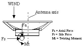
Wind effect on parabolic antennas and support structures can be separated into two force components and a twisting moment as shown.
The side axial and twisting moment forces are maximum values exerted on the supporting structure. In every case the value is the result of the wind from the most critical direction.
All forces are referenced to the mounting column of the antenna
Wind effect on parabolic antennas and supporting structure. Wind force without radome